Alarm panel
Table of Contents
Project Genesis #
After setting up an advanced home alarm system using Home Assistant, I started looking for an alarm panel on the market but couldn’t find one that suited my needs. In fact, most existing panels were either cloud-dependent, too limited in terms of feedback, not easily integrable with Home Assistant, or simply extremely expensive. That’s why I came up with the idea of designing one from scratch using 3D printing and ESPHome for the software part.
NB: Although the final result differs a lot (in terms of usage, software and hardware), this project was inspired by this YouTube video.
Target 🎯 #
Since the possibilities are quite vast (not to say infinite), the first step was to clearly define the requirements:
- Allow the alarm to be activated/deactivated while authenticating the user’s identity,
- Provide clear visual and audible feedback during these actions,
- Display a countdown when the alarm is being activated.

There are several well-known authentication methods:
- “Something you know”: password/code
- “Something you have”: RFID badge
- “Something you are”: Fingerprint/facial recognition
The best option is to combine several of these. As our apartment is not Fort Knox, we decided that an RFID badge attached to the apartment keys was the best option so that we could easily grant access to a third party. The good news is that we already had one for the common area of our building, and I found a way to reuse it. In terms of feedback, we opted for a small buzzer, an LED strip, and a display to show the alarm activation countdown and, as a bonus, fun little animations and the time.
Components 🤖 #
The next step was to identify and purchase all the required components.
To control everything, the idea was to use an ESP32 running ESPHome. ESP32 are energy-efficient microcontrollers that integrate both Wi-Fi and Bluetooth capabilities. Since this project doesn’t need a lot of power and RAM, I opted for an ESP32-S2 Mini.
Here is the list I ended up with (all compatible with ESPHome):
- ESP32-S2 Mini (Link)
- CH1116 1.54" OLED Screen (Link)
- MFRC-522 RFID Reader (Link)
- Active 5V Buzzer 12x9.5mm (Link)
- WS2812B 144LED/m led-strip (Link)
- 24 AWG wires (Link)
- 5 M3 8mm torx screws (Link)
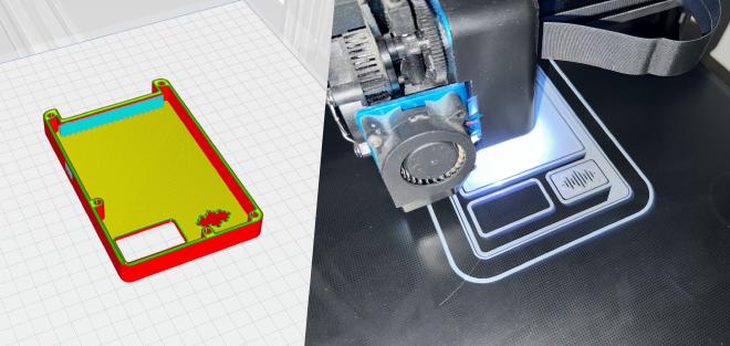
- ELEGOO Matte White PLA (Link)
Once the components had been ordered, it was time to think about the 3D printed alarm panel case that would house them.
Design, 3D Modelling and printing #
In terms of aesthetics, I wanted something simple and modern. In order to get some inspiration, I pitched my ideas to ChatGPT, making sure to list the hardware requirements so that it could generate some renderings:


Apart from the rather old-fashioned grid design, I quite liked the third design (on the right) proposed by ChatGPT so it was time to open Autodesk Fusion360 and start modelling the case.
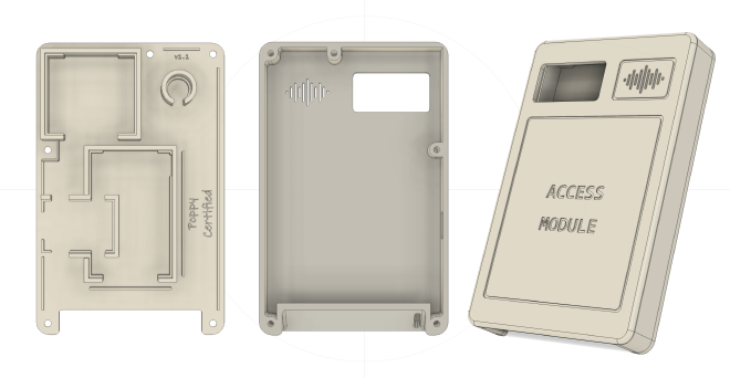
It is composed of two parts:
- The backplate where all components will be placed and held. It also includes narrow cable channels to guide the wiring.
- The faceplate that covers everything. As you can see, the buzzer grid has been redesigned to look like the Spotify logo which I find stylish.
The two parts are assembled together using 5 M3 8mm torx screws.
Wiring & Soldering #
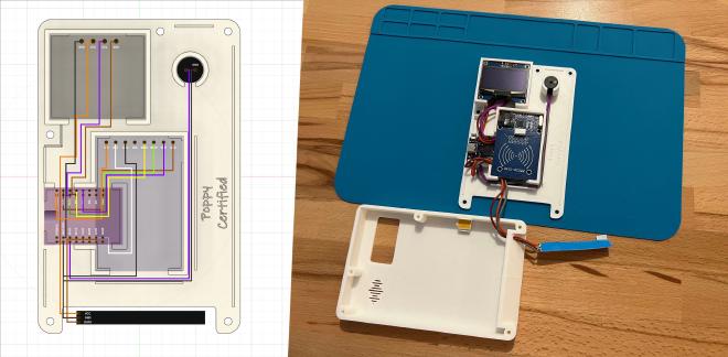
In order to optimize the space inside the case, the wiring was designed in parallel with the 3D modeling.
| CH1116 OLED Screen | ESP32-S2 Mini | Detail |
|---|---|---|
| SDA | GPIO 8 | I2C Data |
| SCL | GPIO 10 | I2C Clock |
| GND | GND | Ground |
| VCC | 5V | 5V Power supply |
| MFRC522 RFID Reader | ESP32-S2 Mini | Detail |
|---|---|---|
| SDA | GPIO 12 | SPI Chip select. pin |
| SCK | GPIO 7 | Clock |
| MOSI | GPIO 11 | Data to MFRC522 |
| MISO | GPIO 9 | Data from MFRC522 |
| RST | GPIO 21 | Reset |
| GND | GND | Ground |
| 3V3 | 3V3 | 3.3V Power supply |
| Active 5V Buzzer | ESP32-S2 Mini | Detail |
|---|---|---|
| GND | GND | Ground |
| VCC | GPIO 16 | 5V Buzzer control |
| WS2812B LED strip | ESP32-S2 Mini | Detail |
|---|---|---|
| DATA | GPIO 37 | Data control |
| VCC | VBUS | 5V Power supply |
| GND | GND | Ground |
Once all cables were soldered, it wasn’t easy to make everything fit inside the case but in the end it worked as planned!
Before screwing everything down, I added an extra layer of opaque stickers inside the case to avoid any light bleeding. A more elegant solution to this problem would have been to print a thin layer of black filament inside the case but this would require a 3D printer capable of printing a single part with multiple filament colors.
The software part: ESPHome #

ESPHome is an open-source system that lets you control and monitor microcontrollers like ESP8266 and ESP32 using simple YAML configuration files. It allows these devices to interact with sensors, switches, displays, and other components, while integrating easily with platforms like Home Assistant.
No traditional code was written for this project, only a long declarative YAML configuration file. Here is a fragment of it, the part that manages the 5V buzzer:
# Configuration that specifies on which GPIO pin the buzzer is plugged.
switch:
  - platform: gpio
    pin: GPIO16
    name: "Buzzer Switch"
    icon: "mdi:volume-high"
    id: buzzer

[...]

# Scripts that are called when an RFID tag is scanned:
# Two short beeps for a valid tag / A long beep for a wrong tag.
script:
  - id: valid_tag_feedback
    then:
      - [...]
      - switch.turn_on: buzzer
      - delay: 100ms
      - switch.turn_off: buzzer
      - delay: 100ms
      - switch.turn_on: buzzer
      - delay: 100ms
      - switch.turn_off: buzzer
      - [...]

  - id: wrong_tag_feedback
    then:
      - [...]
      - switch.turn_on: buzzer
      - delay: 600ms
      - switch.turn_off: buzzer
      - [...]

[...]
Overall, the YAML configuration file describes four alarm panel modes:
| Mode | Alarm state | Display state | LED strip state | Buzzer state |
|---|---|---|---|---|
| Standby | Disabled | Time of the day | Turned off | Turned off |
| Arming | Will be armed in 30sec | 30sec countdown | Orange | Turned off |
| Waiting | Will be triggered in 30sec | Waiting character animation | Orange | Turned off |
| Alert | Triggered, intrusion! | Angry character animation | Blinking red | ON every sec |
Multiple Home Assistant automations have been setup to set the alarm panel mode correctly depending on the current alarm state.
It also describes what to do in case a tag is presented in front of the RFID reader. Its value is read, checked, and a feedback is given accordingly:
| Tag | Display state | LED strip state | Buzzer state |
|---|---|---|---|
| Valid | Happy character animation | Green | Two short beeps |
| Wrong | Sad character animation | Red | One long beep |
In addition to this feedback, an event is sent to Home Assistant that acts in consequence to activate/deactivate the alarm.


Final result ✨ #
Here is the final result we use every day: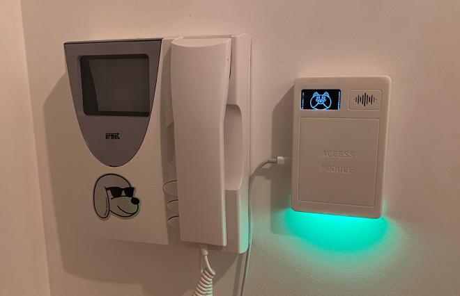
In addition to activating / deactivating the alarm, a set of Home Assistant automations turn off the whole home when we’re leaving / restore the home state when we’re back, making our lives easier :-)
Special thanks to Valeria, who helped me on that project! 😉
Want to dig deeper or build your own?
You’ll find the full project on my GitHub: https://github.com/fbertet/alarm-panel